
Industrial machinery forms the backbone of modern manufacturing and production facilities, yet even the most sophisticated equipment can experience unexpected failures and performance issues. When machinery malfunctions occur, they can result in costly downtime, reduced productivity, and significant financial losses. Understanding the fundamental principles behind machinery operation—particularly input impedance, power consumption patterns, and technical specifications—is essential for any technician tasked with maintaining these complex systems. This guide focuses on practical troubleshooting approaches that address common challenges faced in industrial environments. Whether you're dealing with electrical anomalies, efficiency concerns, or need to interpret technical documentation, the strategies outlined here will help you identify problems quickly and implement effective solutions. By mastering these core concepts and applying systematic diagnostic methods, you'll be better equipped to keep machinery running smoothly, minimize unplanned outages, and extend equipment lifespan while maintaining optimal performance standards across your facility.
Understanding Input Impedance
Input impedance represents the opposition a circuit presents to alternating current flow at its input terminals, measured in ohms. In industrial machinery, this electrical characteristic directly affects signal quality, power transfer efficiency, and overall system performance. When input impedance mismatches occur between connected components, you'll encounter signal distortion, energy loss, and equipment malfunction. Recognizing impedance-related issues requires understanding how different machinery components interact electrically. Sensors, controllers, and monitoring systems all have specific impedance requirements that must align with their connected circuits. A mismatch can cause voltage drops, signal reflections, and inaccurate readings that lead to false diagnostics. Technicians often overlook impedance when troubleshooting, focusing instead on more obvious mechanical failures, yet impedance problems frequently underlie persistent electrical anomalies. High impedance circuits are more susceptible to electromagnetic interference, while low impedance paths can draw excessive current. The impedance value also changes with frequency in AC systems, making it particularly relevant for machinery operating with variable speed drives or high-frequency control signals. By understanding these fundamental principles, you can identify whether erratic sensor readings, communication failures, or power quality issues stem from impedance mismatches rather than component failure, saving time and preventing unnecessary part replacements.
How to Measure Input Impedance
Measuring input impedance requires an impedance analyzer or LCR meter capable of testing at the machinery's operating frequency. Begin by disconnecting power and isolating the circuit you're testing to ensure accurate readings and personal safety. Connect the meter's test leads directly to the input terminals, ensuring solid contact without introducing additional resistance. Set the meter to the appropriate frequency range matching your equipment's specifications—typically 50 or 60 Hz for power systems, but potentially higher for control circuits. Record the impedance magnitude and phase angle, as both values matter for complete circuit analysis. Compare your measurements against manufacturer specifications found in technical documentation. Significant deviations indicate potential problems such as corroded connections, damaged cables, or failing input stages. For dynamic testing, measure impedance under both no-load and operational conditions, as some issues only appear when circuits carry current. Document all readings systematically, creating a baseline reference for future diagnostics. When dealing with complex systems, measure impedance at multiple points along the signal path to pinpoint exactly where mismatches occur, allowing targeted repairs rather than wholesale component replacement.
Power Consumption and Efficiency
Power consumption directly impacts operational costs and reveals underlying machinery health issues before they escalate into catastrophic failures. Industrial equipment drawing excessive power often signals mechanical binding, worn bearings, misalignment, or electrical faults that reduce efficiency and accelerate component degradation. Monitoring power consumption patterns establishes baseline performance metrics that help identify deviations requiring investigation. A motor suddenly consuming 15% more power than normal indicates increased mechanical resistance or electrical problems demanding immediate attention. Modern facilities benefit from continuous power monitoring systems that track consumption in real-time, alerting technicians to anomalies instantly rather than discovering problems during scheduled inspections. Inefficient machinery wastes energy as heat, placing additional stress on cooling systems and creating cascading problems throughout connected equipment. Voltage imbalances, poor power factor, and harmonic distortion all contribute to excessive consumption while degrading component lifespan. Addressing these issues requires systematic analysis of electrical supply quality, load characteristics, and mechanical condition. Regular power audits reveal opportunities for efficiency improvements through better maintenance practices, component upgrades, or operational adjustments. Understanding the relationship between power consumption and mechanical condition enables predictive maintenance strategies that prevent failures rather than reacting to breakdowns, ultimately reducing total cost of ownership while maximizing production uptime and equipment reliability across your entire facility.
Optimizing Power Consumption
Begin optimization by establishing accurate baseline measurements using power quality analyzers that capture voltage, current, power factor, and harmonic content during typical operating cycles. Compare actual consumption against nameplate ratings and manufacturer specifications to identify equipment operating outside normal parameters. Implement variable frequency drives on motors with fluctuating loads, as these devices adjust speed to match demand rather than running continuously at full capacity, typically reducing energy consumption by 20-40% in pumping and fan applications. Address power factor issues by installing capacitor banks that correct reactive power, reducing utility penalties and improving overall system efficiency. Schedule lubrication and alignment checks systematically, as proper maintenance eliminates friction that forces motors to work harder. Replace worn belts, clean heat exchangers, and ensure adequate ventilation to prevent thermal inefficiencies. Install energy-efficient motors meeting NEMA Premium standards when replacing failed units, as the energy savings quickly offset higher initial costs. Monitor operating temperatures using thermal imaging to detect hotspots indicating electrical resistance or mechanical friction consuming excess power. Consolidate operations during off-peak hours when possible to benefit from lower utility rates while reducing demand charges that penalize peak consumption periods. Many facilities integrate PLC-based automation systems from providers like Moore Automated to coordinate equipment operation, optimize scheduling, and monitor power consumption across multiple machines simultaneously, enabling more sophisticated energy management strategies.
Technical Specifications of Bently Nevada Machinery
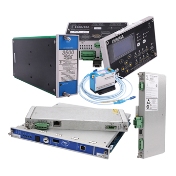
Bently Nevada machinery stands at the forefront of condition monitoring and asset protection systems, designed specifically for rotating equipment in industrial environments. These sophisticated systems incorporate proximity probes, accelerometers, and monitoring modules that continuously assess machinery health through vibration analysis, temperature tracking, and position monitoring. Understanding the technical specifications of these systems is fundamental to effective troubleshooting, as many perceived machinery problems actually stem from improper sensor installation, incorrect configuration parameters, or misinterpretation of monitoring data. The systems typically operate on 24V DC power supplies with specific current requirements that must be maintained within tolerance for accurate readings. Proximity probes require precise gap voltage settings, usually between 7-9V DC, to function correctly, and deviations outside this range indicate wiring issues, damaged cables, or failing probe elements. Accelerometers have specific frequency response ranges, sensitivity ratings measured in millivolts per g-force, and mounting requirements that directly affect measurement accuracy. Monitor modules process signals according to programmed alarm setpoints, scaling factors, and filtering parameters that must align with machinery characteristics and operational conditions. Temperature specifications define operating ranges typically from -30°C to +65°C for electronics, though sensors may handle more extreme conditions. Communication protocols including Modbus, proprietary Bently protocols, and modern Ethernet-based systems require specific configuration for integration with plant control systems. Grounding requirements are particularly critical, as improper grounding introduces noise that corrupts sensor signals, leading to false alarms and diagnostic confusion. Cable specifications dictate maximum run lengths, shielding requirements, and connector types that ensure signal integrity across industrial distances.
Key Technical Specifications
Voltage requirements for Bently Nevada monitoring systems typically demand 18-30V DC input with ripple less than 10%, ensuring stable operation without introducing electrical noise into sensitive measurement circuits. Operational temperature ranges for monitor racks span -30°C to +65°C ambient, while sensors themselves often withstand -40°C to +85°C, making proper environmental control essential in extreme conditions. Load capacities vary by module type, with standard racks supporting 8-16 monitor modules drawing approximately 5-10 watts each, requiring adequate power supply sizing during system design. Proximity probe systems operate at 200 kHz oscillation frequency with -24V DC supply voltage, producing gap voltage inversely proportional to target distance. Accelerometer specifications include frequency response from 2 Hz to 10 kHz for standard vibration monitoring, with sensitivity ratings of 100 mV/g being common for general-purpose applications. Understanding these specifications enables technicians to verify proper installation, diagnose sensor failures versus wiring problems, and configure alarm setpoints appropriately based on machinery characteristics rather than arbitrary values that generate nuisance alarms or miss developing faults. The 3500/25 149369-01 enhanced keyphasor module exemplifies these principles with its precise specifications for shaft speed monitoring and phase reference measurements in rotating machinery applications.
Mastering Industrial Machinery Troubleshooting
Effective troubleshooting of industrial machinery hinges on mastering three fundamental areas: input impedance analysis, power consumption monitoring, and thorough understanding of technical specifications. By systematically measuring input impedance and identifying mismatches, you prevent signal degradation and electrical anomalies that compromise system performance. Monitoring power consumption patterns provides early warning signs of mechanical wear, electrical faults, and efficiency losses before they escalate into costly failures. Understanding technical specifications—particularly for sophisticated monitoring systems like Bently Nevada equipment—ensures proper installation, accurate configuration, and correct interpretation of diagnostic data. These interconnected concepts form the foundation of predictive maintenance strategies that shift your approach from reactive repairs to proactive problem prevention. Implementing the measurement techniques, optimization strategies, and specification guidelines detailed throughout this article will reduce unplanned downtime, extend equipment lifespan, and significantly lower operational costs. The investment in proper diagnostic tools, systematic documentation, and continuous monitoring pays dividends through improved reliability and production efficiency. As industrial machinery grows increasingly complex, your ability to apply these fundamental troubleshooting principles becomes ever more valuable, positioning you to maintain peak performance across your facility while minimizing the financial impact of equipment failures.